

Electrical Engineering: Electronics and Semiconductors
Transitioning from Passive Circuits to Active Semiconductor Components and Digital Logic.

Happy Wednesday!
Insight Trunk is a free lifetime library—a modern replacement for outdated encyclopedias. From Monday to Saturday, we deliver a 10-minute read on a specific subject, with fresh topics each week. Two years later, we revisit each theme with updated insights from our archives—so you’ll never miss a thing. You can unsubscribe anytime using the link at the bottom of this newsletter.
Today, we shift from passive circuits to active components. You’ll explore the fundamental operation of diodes for rectification, see how transistors act as switches and amplifiers, master the power of Op-Amps, and get introduced to basic digital logic gates.
🧑💻 In this week’s edition: Electrical Engineering
Monday - Fundamentals of Electricity
Tuesday - DC and AC Circuit Analysis
Wednesday - Electronics and Semiconductors
Thursday - Digital Systems and Microcontrollers
Friday - Electromagnetics and Machines
Saturday - Signal Processing and Communications
Question of the day
What is the primary function of a Bipolar Junction Transistor (BJT) when its base is saturated?
Let’s find out !
Electronics and Semiconductors
Let’s break it down in today discussion:
Diode Fundamentals and Rectification
The Transistor: Switching and Amplification
The Versatile Operational Amplifier (Op-Amp)
Foundational Digital Logic Gates
Read Time : 10 minutes
➡️ Diode Fundamentals and Rectification
The diode represents the simplest form of a nonlinear, two-terminal semiconductor device, crafted by forming a junction between P-type (positive majority carriers) and N-type (negative majority carriers) semiconductor materials. This P-N junction exhibits a remarkable property: it allows current flow almost exclusively in one direction.
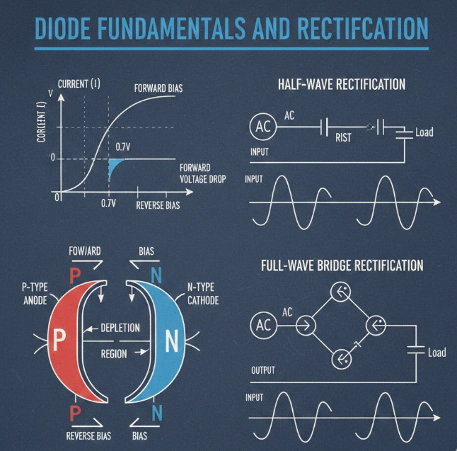
The operation depends on the applied voltage bias. In forward bias, the positive terminal is connected to the P-material, and the negative to the N-material. Once the applied voltage exceeds the cut-in voltage, the diode’s resistance drops significantly, allowing current to flow. Conversely, in reverse bias, the diode behaves like an open switch, blocking almost all current flow until the high breakdown voltage is reached.
The most fundamental application of this unidirectional characteristic is rectification, the process of converting an Alternating Current (AC) signal into a pulsating Direct Current (DC) signal. Rectifier circuits, such as half-wave and full-wave configurations, are the initial stages in nearly every power supply, transforming the AC line voltage into a usable DC level for electronic components. Specialized variants, such as the Zener diode, are engineered to operate in the reverse breakdown region for precise voltage regulation.
Want to go beyond the basics? This video is a great resource.
⚙️ The Transistor: Switching and Amplification
The transistor is the central component of modern electronics, functioning primarily as a solid-state switch or an amplifier. The two predominant types are the Bipolar Junction Transistor (BJT) and the Metal-Oxide-Semiconductor Field-Effect Transistor (MOSFET).
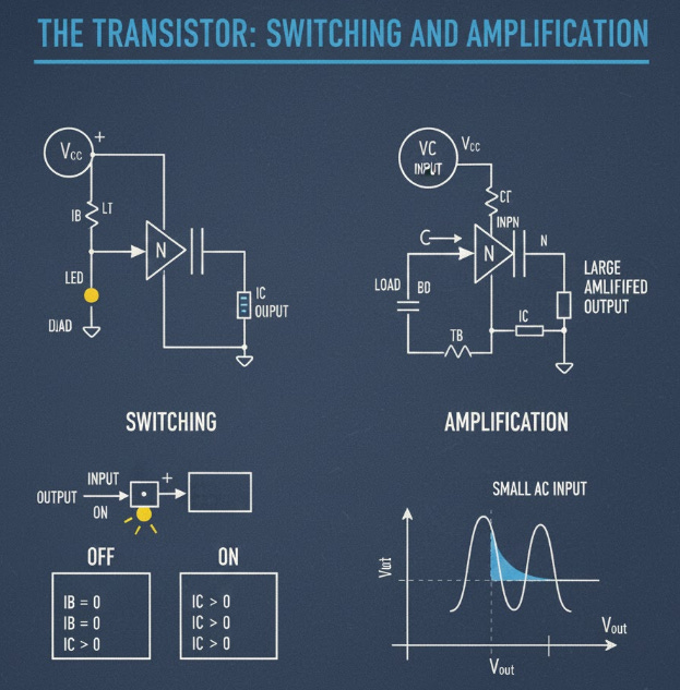
As a digital switch, the transistor operates in distinct regions based on the control input at its gate (MOSFET) or base (BJT). In the cut-off region, the device is essentially an open circuit, blocking current flow and representing the digital state ‘0’ (FALSE). Conversely, in the saturation region, the device is driven hard into conduction, acting as a low-resistance closed circuit, representing the digital state ‘1’ (TRUE). This fundamental ON/OFF capability is what enables all digital logic and memory.
Beyond switching, the transistor excels at amplification. Operating in the active region, a small change in the input signal (voltage for MOSFET, current for BJT) produces a significantly larger, proportional change in the output current. This allows the device to boost weak electrical signals without introducing substantial distortion, which is essential in radio receivers, audio equipment, and sensor interfaces.
For an in-depth look, make sure to watch this video.
➕ The Versatile Operational Amplifier (Op-Amp)
The Operational Amplifier (Op-Amp) is a ubiquitous, high-performance integrated circuit (IC) that serves as the fundamental building block for a vast array of analog circuits. It is essentially a differential amplifier, meaning it amplifies the difference between its two input terminals.
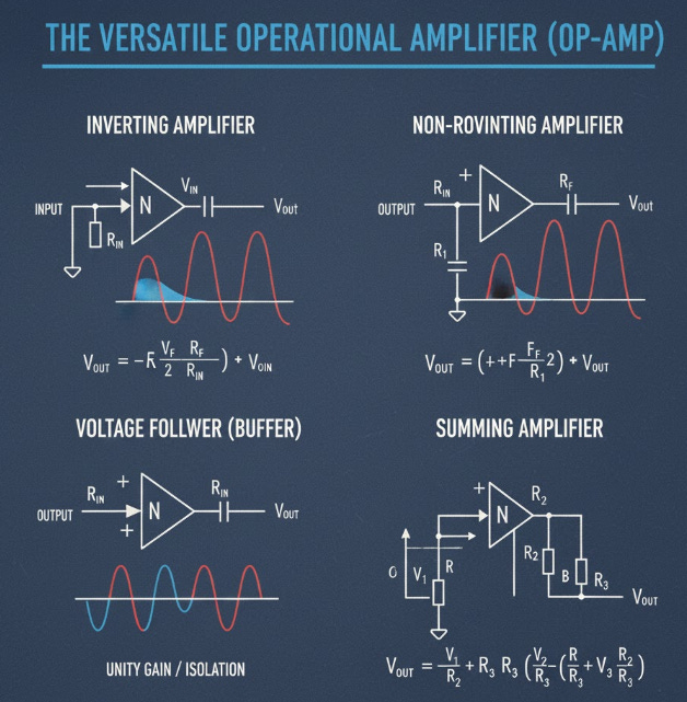
For practical analysis, the Op-Amp is often approximated by its ideal characteristics. Key among these are infinite open-loop voltage gain, infinite input impedance (meaning zero current flows into the input terminals), and zero output impedance. When configured with negative feedback (connecting the output back to the inverting input), the Op-Amp adheres to two crucial golden rules: the differential input voltage is zero, and the input currents are zero.
These rules simplify complex circuit analysis, allowing the Op-Amp to be used in numerous configurations. Common applications include the inverting amplifier, which changes the sign of the input signal while amplifying it, and the non-inverting amplifier, which maintains the input signal’s phase. Other vital roles include precision voltage followers, active filters, and the creation of summing and difference amplifiers that perform actual mathematical operations on electrical signals.
Broaden your understanding by watching this video.
🔢 Foundational Digital Logic Gates
The manipulation and processing of information in modern computing rely on digital logic, which represents data using discrete binary states: Logic High (1) and Logic Low (0). The physical implementation of these states is achieved using transistor-based circuits known as logic gates.
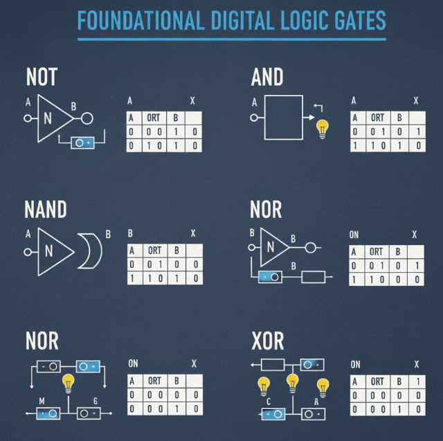
Logic gates perform fundamental Boolean algebra operations. The AND gate is a core component whose output is TRUE (1) only if every one of its inputs is TRUE. If any input is FALSE (0), the output will be FALSE. This function is analogous to multiplication in Boolean algebra. Conversely, the OR gate produces a TRUE (1) output if one or more of its inputs are TRUE. Its output is only FALSE (0) if all of its inputs are simultaneously FALSE.
These simple building blocks—along with the fundamental NOT gate (inverter), which simply reverses the input state—can be combined to create any complex digital system. For instance, the combination of AND, OR, and NOT gates allows for the construction of arithmetic circuits like adders, and memory elements like flip-flops. Mastery of these gates is the essential starting point for understanding how microprocessors and digital devices function.
Ready to learn more? Dive into this video.
Summary
The One-Way Valve (Diodes)
The diode is the simplest semiconductor device formed by a P-N junction.
It conducts easily in forward bias and blocks current in reverse bias.
Its key function is rectification, which converts AC signals into pulsating DC signals.
Diodes are the initial stage for transforming household power into usable power for electronics.
Transistors as Controllers
Transistors (BJT/MOSFET) serve as crucial components for both switching and signal amplification.
For digital switching, the transistor is either fully ON (saturation) or fully OFF (cut-off).
When used for amplification, a small input signal controls a much larger output current flow.
The switching function is the foundational element of all digital systems and computing.
The Versatility of Op-Amps
The Operational Amplifier (Op-Amp) is an integrated circuit used primarily in analog applications.
It is characterized by high gain and high input impedance in its ideal model.
With negative feedback, two simple rules apply: input currents are zero, and input voltages are equal.
Op-Amps are versatile for building active filters, summing, and precision amplifiers.
Introduction to Digital Logic
Logic gates physically implement binary operations using transistor switching actions.
The AND gate requires all inputs to be TRUE (1) to produce a TRUE output.
The OR gate only requires one or more inputs to be TRUE (1) for a TRUE output.
These basic gates form the algebraic language and building blocks for all complex digital systems.
Hacks for Identifying Op-Amp Circuit Configurations.
Inverting Amplifier Check: Look for the input signal connected to the inverting terminal (V-) through a resistor, with feedback connected from output to V-.
Non-Inverting Amplifier Check: Look for the input signal connected directly to the non-inverting terminal (V+), with the feedback network still attached to V-.
Voltage Follower ID: If the output is connected directly back to the V- terminal, and the input is at V+, the gain is one (unity).
Comparator ID: If there is no feedback resistor between the output and the inverting terminal, it’s typically operating as an open-loop comparator.
Summing Amplifier ID: If multiple input resistors converge and connect to the inverting terminal (V-), it is summing the inputs.
Answer of the day
What is the primary function of a Bipolar Junction Transistor (BJT) when its base is saturated?
Acts as a closed switch.
When a BJT’s base is saturated, it means a sufficient current is applied to fully turn it on. In this operating region, the transistor acts like a near-ideal closed switch, allowing maximum current to flow between the collector and emitter, a key mechanism in digital electronics.
That’s A Wrap!
Want to take a break? You can unsubscribe anytime by clicking “unsubscribe” at the bottom of your email.
Excellent pedagogical approach to semiconductor fundamentals. The progression from diode rectification through transistor switching to op-amp configurations builds intuition systematically. What strikes me most is how you frame saturation and cutoff regions as the foundation for all digital logic, which elegantly connects the physics layer to the abstraction layer. The emphasis on forward versus reverse bias creating unidirectional current flow makes the P-N junction behavior immediately graspable. One nuance worth highlighting is that while your idealop-amp model with infinite gain and zero input current simplifies analysis beautifully, real world implementations face bandwidth limitations and input bias currents that become critical in precision applications. The logic gate section bridges nicely to next week's digital systems topic, especially sincethe AND/OR gate truth tables directly map to Boolean algebra operations. Curious whether you'll cover CMOS transistor pairs in the digital systems section, as understanding complementry pull-up/pull-down networks really solidifies how gates minimize power consumption.