

Electrical Engineering: Digital Systems and Microcontrollers
From Binary Code to Computational Systems: Logic and Microcontroller Architecture.

Happy Thursday!
Insight Trunk is a free lifetime library—a modern replacement for outdated encyclopedias. From Monday to Saturday, we deliver a 10-minute read on a specific subject, with fresh topics each week. Two years later, we revisit each theme with updated insights from our archives—so you’ll never miss a thing. You can unsubscribe anytime using the link at the bottom of this newsletter.
We convert everything to binary today, starting with different number systems. You’ll learn to build circuits using combinational logic and store data with sequential logic elements like flip-flops. Finally, we introduce the architecture of microcontrollers.
🧑💻 In this week’s edition: Electrical Engineering
Monday - Fundamentals of Electricity
Tuesday - DC and AC Circuit Analysis
Wednesday - Electronics and Semiconductors
Thursday - Digital Systems and Microcontrollers
Friday - Electromagnetics and Machines
Saturday - Signal Processing and Communications
Question of the day
What type of logic circuit is used to create a one-bit memory cell?
Let’s find out !
Digital Systems and Microcontrollers
Let’s break it down in today discussion:
Number Systems in Digital Engineering
Combinational Logic Circuit Design
Sequential Logic: Memory and State
Microcontroller Architecture and Function
Read Time : 10 minutes
🔢 Number Systems in Digital Engineering
The fundamental language of all digital systems is the binary system (base-2), which utilizes only two discrete digits, 0 and 1. This system is intrinsically tied to the physical realization of digital circuits, where 0 and 1 correspond directly to the OFF and ON states (low and high voltage levels) of a transistor. Effective communication and system interpretation necessitate understanding how to relate this binary data to other conventions.
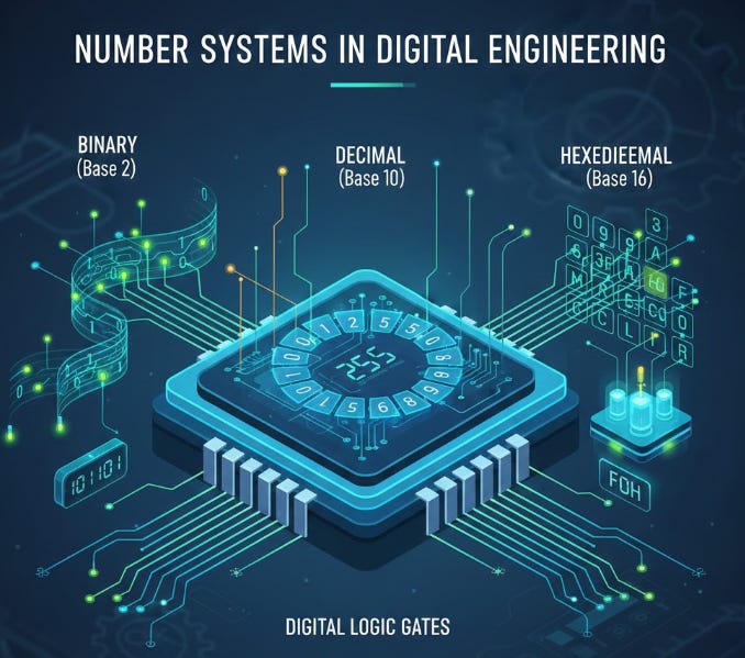
The decimal system (base-10) is the conventional arithmetic system for human communication, employing ten digits (0-9). Conversion between binary and decimal is crucial for input and output operations.
For programmers and engineers working with large amounts of binary data, the hexadecimal system (base-16) is a vital shorthand. Using 0-9 and A-F, hexadecimal compactly represents groups of four binary digits (bits). For example, the binary sequence 1111 0000 (eight bits) is much more succinctly written as F0_16. This conversion efficiency dramatically reduces transcription errors and simplifies the reading of memory addresses and data registers.
This video offers comprehensive details on the subject.
🧩 Combinational Logic Circuit Design
Combinational logic is a fundamental class of digital circuit where the output values are determined solely by the current state of the input signals. Unlike sequential logic, these circuits lack any form of memory or feedback mechanisms.
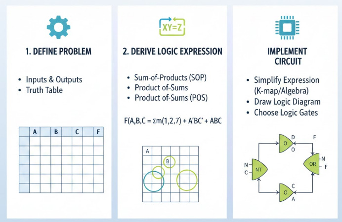
The design and analysis of combinational logic rely heavily on Boolean algebra, a mathematical system where variables and functions can assume only two values: logical TRUE (1) or FALSE (0). Boolean identities and theorems are utilized to simplify complex logical expressions, reducing the required number of physical gates (such as AND, OR, and NOT) necessary to implement the function. This optimization minimizes cost, power consumption, and propagation delay in integrated circuits.
Key components constructed from combinational logic include adders (which perform binary addition), decoders (which convert N binary inputs into 2^N unique outputs), and multiplexers (MUXs), which select one of several input lines and route it to a single output line based on a select control signal. The rigorous, fixed relationship between input and output makes these circuits essential for implementing arithmetic and data routing functions within a digital system.
Unpack the complexities with the help of this video.
💾 Sequential Logic: Memory and State
In contrast to combinational logic, sequential logic circuits are characterized by their dependence on both the present input and the past state of the circuit. This temporal dependence is achieved through feedback loops, providing the critical function of memory in digital systems.
The most fundamental memory element is the flip-flop (or latch), which is capable of storing a single bit of binary information (a 0 or a 1). Key flip-flop types, such as the D (Data) flip-flop, are often edge-triggered, meaning they capture the input data only at the rising or falling edge of an external clock signal. This synchronization ensures orderly data transfer and storage across the entire system.
By cascading multiple flip-flops, two essential components are constructed: registers and counters. A register is an array of flip-flops used to store a multi-bit binary word, essential for holding data, addresses, or instructions within a processor. A counter is a specialized register whose state advances sequentially upon each clock pulse, making it indispensable for measuring time intervals, counting events, and controlling operation sequences within hardware.
Take your learning further by watching this video.
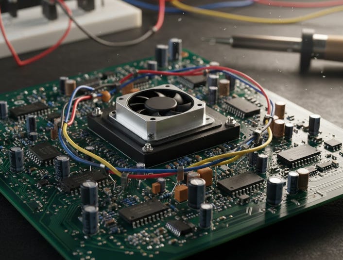
🧠 Microcontroller Architecture and Function
A microcontroller (MCU) is a highly integrated, compact computer system contained entirely on a single integrated circuit chip. Unlike microprocessors, which rely on external chips for memory and peripherals, the MCU is designed for embedded applications, where size and dedicated control are paramount.
The typical MCU architecture incorporates a Central Processing Unit (CPU), various forms of memory (volatile RAM for temporary data and non-volatile Flash/ROM for program storage), and essential input/output (I/O) peripherals. The CPU operates on a fetch-decode-execute cycle: it retrieves instructions from the program memory, interprets the instruction (decode), and performs the corresponding arithmetic, logic, or data transfer operation (execute).
The integrated peripherals enable the MCU to interact with the external world. These can include timers for precise control of time intervals, Analog-to-Digital Converters (ADCs) for reading sensor data, and communication interfaces (UART, SPI, I2C) for transmitting and receiving data. The MCU executes a stored program to read inputs (e.g., temperature from an ADC), process the logic (e.g., check if temperature exceeds a threshold), and generate outputs (e.g., turn on a fan via a digital output pin).
For a complete overview, watch this video.
Summary
The Language of Digital Systems
The binary system (0 and 1) is the foundational language because it directly reflects the ON/OFF states of transistors.
The decimal system (base-10) is the standard for human interaction and requires conversion to binary for machine use.
The hexadecimal system (base-16) is a convenient shorthand for programmers to easily read and write long binary strings.
Understanding conversion between these bases is essential for data interpretation and digital hardware debugging.
Logic without Memory (Combinational)
Combinational logic circuits have outputs that depend only on their current inputs.
These circuits have no feedback or memory elements to retain past states.
Their operation is governed by Boolean algebra, which is used to simplify the gate implementation.
Key applications include arithmetic components like adders and data routing circuits like multiplexers.
Logic with Memory (Sequential)
Sequential logic outputs depend on the present inputs and the previous state of the system due to internal feedback.
The flip-flop is the fundamental memory cell, capable of storing a single bit of information (0 or 1).
Registers are groups of flip-flops used together to store larger multi-bit binary words.
Counters are specific sequential circuits designed to track the number of clock pulses, essential for timing and control.
The Embedded Computer (Microcontrollers)
A microcontroller (MCU) is a complete computer system integrated onto a single chip for embedded control.
Its architecture includes the CPU, memory (RAM/Flash), and various I/O peripherals.
The CPU executes the stored program using a continuous fetch-decode-execute cycle.
MCUs interact with the real world by reading signals via ADCs and controlling devices via digital outputs.
Microcontroller Pin Configuration Quick Reference Tips.
Understand Multiplexing: Recognize that most microcontroller pins have multiple functions (e.g., GPIO, ADC, PWM) and the function is selected via register configuration.
Always Check Datasheets: The primary source for reliable pin mapping and electrical limitations is always the official device datasheet from the manufacturer.
Power and Ground First: Before connecting any peripherals, always ensure the VCC (power) and GND (ground) pins are correctly connected and stabilized.
Reset Pin Management: Be aware of the reset pin’s state, as it must typically be pulled high (connected to VCC) via a resistor to allow the MCU to execute its program.
Input vs. Output Setup: Explicitly configure each General-Purpose Input/Output (GPIO) pin as either an input (high impedance) or an output (driving capability) in your initial code setup.
Answer of the day
What type of logic circuit is used to create a one-bit memory cell?
Sequential logic, specifically a flip-flop.
A flip-flop is the fundamental building block of sequential logic, unlike combinational circuits which have no memory. This element uses feedback to hold a stable state, allowing it to store a single bit of binary information (0 or 1), which is essential for registers and counters.
That’s A Wrap!
Want to take a break? You can unsubscribe anytime by clicking “unsubscribe” at the bottom of your email.