

Electrical Engineering: DC and AC Circuit Analysis
Advanced DC Analysis Methods and the Transition to Alternating Current (AC) Principles.

Happy Tuesday!
Insight Trunk is a free lifetime library—a modern replacement for outdated encyclopedias. From Monday to Saturday, we deliver a 10-minute read on a specific subject, with fresh topics each week. Two years later, we revisit each theme with updated insights from our archives—so you’ll never miss a thing. You can unsubscribe anytime using the link at the bottom of this newsletter.
Today, we’re leveling up from Ohm’s Law to tackle complex circuits. Today’s focus is on mastering Kirchhoff’s Laws for detailed DC analysis, simplifying networks with Thevenin and Norton equivalents, and transitioning into the fundamental concepts of Alternating Current (AC) and Phasors.
🧑💻 In this week’s edition: Electrical Engineering
Monday - Fundamentals of Electricity
Tuesday - DC and AC Circuit Analysis
Wednesday - Electronics and Semiconductors
Thursday - Digital Systems and Microcontrollers
Friday - Electromagnetics and Machines
Saturday - Signal Processing and Communications
Question of the day
What is the necessary first step before applying the nodal analysis technique to a complex circuit?
Let’s find out !
DC and AC Circuit Analysis
Let’s break it down in today discussion:
Systemic Analysis with Kirchhoff’s Laws
Network Simplification: Thevenin and Norton Theorems
The Nature of Alternating Current (AC)
Phasor Representation and Complex Impedance
Read Time : 10 minutes
📐 Systemic Analysis with Kirchhoff’s Laws
For the analysis of circuits containing multiple sources and interconnected components, Kirchhoff’s Laws provide a definitive and systematic approach. These laws are extensions of fundamental physical principles: the conservation of electric charge and the conservation of energy.
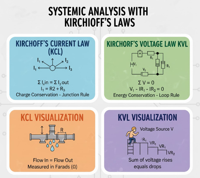
Kirchhoff’s Current Law (KCL) enforces the conservation of charge at any junction, or node, within a circuit. KCL states that the algebraic sum of currents entering a node must be identically zero. This principle forms the basis for Nodal Analysis, a technique where the unknown voltages at the primary nodes are defined and solved using KCL equations. For example, if I1 and I2 enter a node and I3 leaves it, KCL dictates that I1 + I2 - I3 = 0.
Kirchhoff’s Voltage Law (KVL) is based on the conservation of energy and applies to any closed path, or mesh, in a circuit. KVL states that the algebraic sum of all voltage drops and rises around any closed loop must equal zero. This principle underpins Mesh Analysis, a method used to define and solve for the unknown circulating currents within each independent closed loop. The result is a set of simultaneous linear equations, which can be solved matrix methods, providing a complete solution for all currents and voltages in the DC circuit.
Learn more about what we discussed by watching this video!
🔌 Network Simplification: Thevenin and Norton Theorems
In the analysis and design of complex electrical circuits, it is frequently advantageous to simplify a substantial portion of the network into an easily solvable equivalent model. Thevenin’s Theorem and Norton’s Theorem provide powerful tools for achieving this simplification, reducing any linear two-terminal network of sources and resistances into a single, straightforward equivalent.
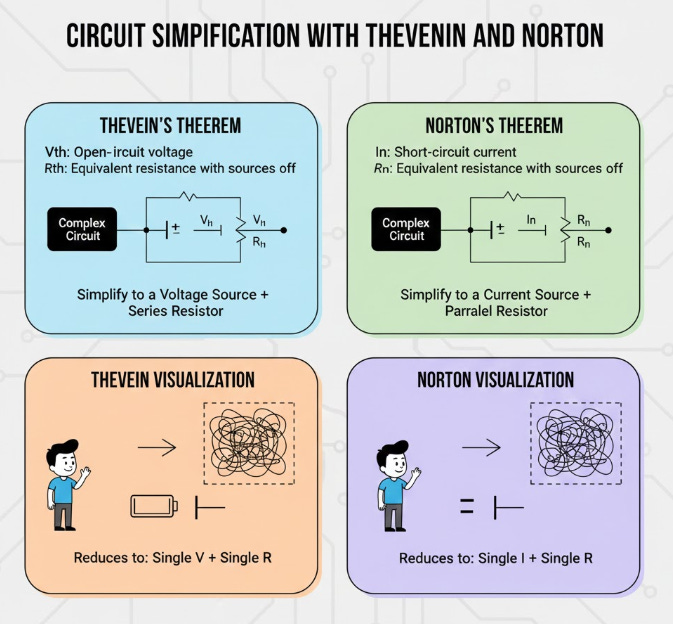
Thevenin’s Theorem postulates that any linear two-terminal circuit can be replaced by an equivalent circuit consisting of a single voltage source, V (the open-circuit voltage at the terminals), connected in series with a single resistor, R(the equivalent resistance looking back into the circuit with all independent sources turned off). This equivalent makes it trivial to calculate the voltage and current for any external load resistor connected to the terminals.
Conversely, Norton’s Theorem offers an alternative but equally valid representation: the linear two-terminal circuit can be replaced by a single current source, IN (the short-circuit current between the terminals), connected in parallel with a single resistor, RN. It is important to note the direct relationship between the two models: R = RN, and V= IN x R. These equivalency methods are crucial for maximizing power transfer and isolating system components for focused analysis.
For a deeper understanding, check out this video.
📈 The Nature of Alternating Current (AC)
While Direct Current (DC) maintains a constant voltage and current magnitude over time, Alternating Current (AC) is characterized by periodic and sinusoidal variation. The primary distinction is that AC voltage and current periodically reverse their direction, making it the preferred method for long-distance power transmission and distribution.

The waveform of an AC signal is defined by several key parameters. Frequency (f), measured in Hertz (Hz), quantifies the number of complete cycles the waveform completes per second. The reciprocal of frequency is the Period (T), which is the time duration of one complete cycle. For instance, standard household power in North America operates at 60Hz, meaning the voltage completes 60 full cycles every second.
The magnitude of the AC signal is usually described using the Root Mean Square (RMS) value. The RMS value is the equivalent DC value that would produce the same heating effect (power dissipation) in a resistor. This RMS value is the practical measure cited for system specifications, such as 230 V AC in many international standards.
This video will give you further insights into the topic.
ℂ Phasor Representation and Complex Impedance
The inclusion of energy storage components (capacitors and inductors) in AC circuits introduces a phase shift between the voltage and current waveforms. To manage this complexity, engineers employ Phasors and the concept of Complex Impedance to simplify analysis.
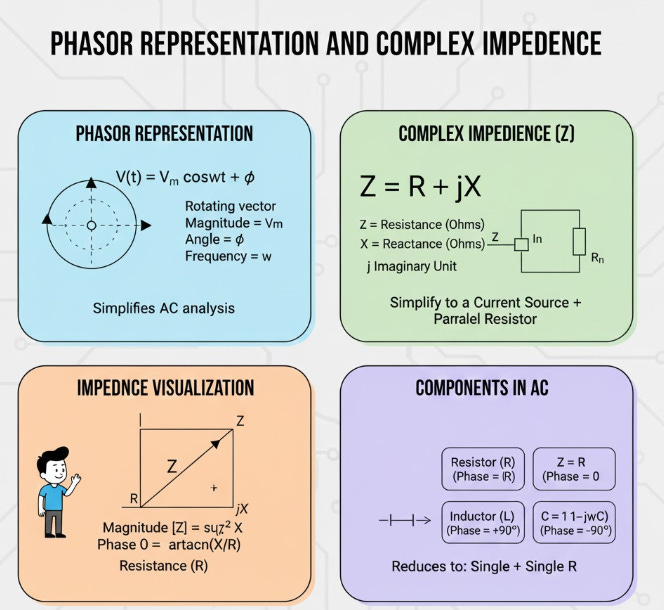
A Phasor is a rotating vector that graphically represents a sinusoidal waveform by capturing both its magnitude (amplitude) and its phase angle. By using phasors, the time-dependent differential equations governing AC circuits are transformed into algebraic equations involving complex numbers. This conversion is crucial because it allows the manipulation of voltage and current using simple vector addition and subtraction, just as in DC analysis.
Complex Impedance (Z), measured in Ohms (Omega), is the AC equivalent of resistance. Impedance accounts not only for the purely resistive component (R, the real part) but also for the reactance (X, the imaginary part) introduced by capacitors and inductors. Resistance causes energy dissipation, while reactance causes the phase shift. This generalized concept allows Ohm’s Law to be applied in the complex domain: V = I x Z.
Learn more about what we discussed by watching this video!
Summary
Kirchhoff’s Laws for Complex Circuits
Kirchhoff’s Current Law (KCL) enforces the conservation of charge at a node.
KCL is the core principle used in Nodal Analysis to solve for unknown node voltages.
Kirchhoff’s Voltage Law (KVL) enforces the conservation of energy around a closed loop.
KVL is the core principle used in Mesh Analysis to solve for unknown loop currents.
These methods allow for the creation and solution of simultaneous linear equations for any complex DC network.
Network Simplification Theorems
Thevenin’s Theorem simplifies a complex network into an equivalent voltage source and series resistor.
Norton’s Theorem simplifies the same network into an equivalent current source and parallel resistor.
These theorems allow engineers to calculate the behavior of a load without re-analyzing the entire internal circuit.
The Thevenin and Norton resistances are always equal.
Fundamentals of Alternating Current (AC)
AC voltage and current vary sinusoidally over time and periodically reverse direction.
Frequency (f) is the rate of cycles per second, and Period (T) is the time for one cycle.
The RMS (Root Mean Square) value represents the effective power-delivering capability of the AC signal.
AC is the most common form of electricity used for large-scale power distribution.
AC Circuit Tools: Phasors and Impedance
Impedance (Z) is the AC equivalent of resistance, accounting for magnitude and phase shift.
Phasors are complex numbers used to represent AC voltage and current with both magnitude and phase angle.
Phasors transform complex time-domain differential equations into simpler complex algebraic equations.
Impedance allows Ohm’s Law (V = I x Z) to be applied directly in the AC complex domain.
Tips and Tricks for Applying Kirchhoff’s Laws.
Node Voltage (KCL) Tip: Always assign one node as the reference node (ground, 0 V) to minimize the number of unknown voltages you need to solve for.
Mesh Current (KVL) Tip: Ensure that all current sources are handled early, either by converting them to equivalent voltage sources or by treating the loop they inhabit as a “supermesh.”
Direction Consistency: Arbitrarily select a direction for all unknown currents (e.g., clockwise for meshes, or leaving the node for nodal analysis) but be meticulously consistent throughout your setup.
Source Conversion Hack: If a circuit has only one type of source (all voltage or all current), consider using the corresponding analysis method (Mesh for voltage, Nodal for current) to slightly simplify the setup.
Check Your Math: After finding the currents, use the calculated values to verify KVL around a separate, unused loop or check KCL at a different node to confirm your solution’s accuracy.
Answer of the day
What is the necessary first step before applying the nodal analysis technique to a complex circuit?
Identify and define all non-reference nodes.
Nodal analysis is based on Kirchhoff’s Current Law (KCL) at each non-reference node (junction). Defining these nodes is crucial because the technique solves for the unknown voltages at these specific points, allowing the subsequent calculation of every current and voltage in the circuit.
That’s A Wrap!
Want to take a break? You can unsubscribe anytime by clicking “unsubscribe” at the bottom of your email.